 Made In The USA

Application Notes

Redundant Power Supplies — Considerations When Paralleling Power Supply Outputs for Redundancy

Although the extremely high overall reliability that can be attained with redundancy is widely recognized, implementing redundancy is not always as easy as it may first appear to be. In particular, it takes more than simply paralleling the outputs of two or more power supplies to have a redundant power system that will function as intended.
An isolation diode must be used in series with the output of each power supply, for two reasons - to avoid the possibility of the combined output being shorted by a shorted supply, and to prevent current from one supply flowing back into another and reverse biasing it (which could cause it to malfunction). However, the use of diodes introduces a significant voltage drop in the output voltage from the supply; for example, a 5 volt output might drop to only 4 volts. Using Schottky diodes can in some cases mitigate the diode drop, but it must still be considered. And keep in mind that the supply must be capable of providing a voltage equal to the sum of the voltage required across the load, the diode drop AND the drops in the wiring. A typical power supply can compensate up to a volt or so of drops in the wiring, but may not be capable of compensating BOTH the wiring and the diode drops. And if you’re using remote sensing to regulate the voltage across the load, you might not be able to solve this problem by simply stepping up to a supply with a higher nominal output voltage (for example, going from a 5 volt supply to a 6 volt supply), because then the sense lines of that supply would try to maintain a nominal 6 volts across the load! In summary, be sure to use a supply that can put out a voltage high enough to compensate both the diode and wiring drops under worst-case conditions (usually, low line and maximum load current), and also has the desired load voltage within its adjustment range.
Monitoring each power supply’s output is also very important. Otherwise, you might not even know that one power supply is out until the other goes, and then it’s too late – you’re down! Voltmeters are helpful, of course, but they don’t command your attention. An audible alarm can’t be easily ignored. Include an undervoltage alarm circuit for each power supply, and use them to control an audible alarm, either built-in or remotely located where it will be heard.
Power supplies don’t always go low when they fail; the voltage can instead go high – by 50% or more in some cases – and fry the load. Therefore, it’s vitally important that power supplies used in redundant applications should always be equipped with fast-acting overvoltage protection to assure that the output voltage can’t go much higher than the nominal.
Replacing an inoperative power supply while the system remains in operation requires that each power supply have a separate AC input switch, so that the inoperative supply’s wiring can be deactivated without affecting the other(s). Similarly, it must be possible to disconnect the inoperative supply and connect the replacement quickly and easily, so insulated connectors that can be easily pulled apart should be used in the wiring to each supply. And the supplies should be mounted in such a way that they can be easily and quickly removed and replaced. One way of doing this is to use thumbscrews for mounting; this also eliminates the need for tools.
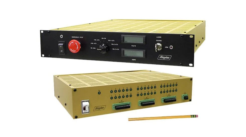
Comprehensively addressing all of these considerations can be a lot of work. However, you don’t need to do it yourself. Acopian’s standard Redundant Systems meet all of these requirements, and are available with outputs from 5 to 125 VDC and in a choice of mechanical configurations (rack mounting, wall mounting and modular systems that can be mounted on a DIN rail).