 Made In The USA


Modular Redundant Power Supply Systems
AC-DC single output
- Shipped Within 9 Days
- Five Year Warranty
5v to 125v Models
3.3v to 125v Models
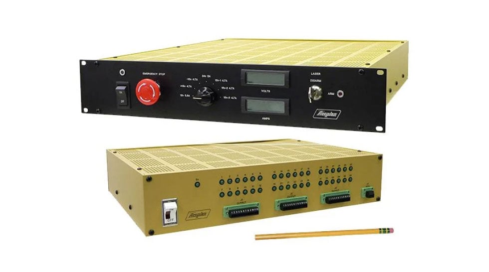
MAIN SCREEN
Extremely high overall reliability results from connecting two power sources so that one will continue to provide power to their load even if the other becomes inoperative. Redundancy may be restored by replacing or repairing the inoperative source while the system remains in operation. A redundant power system should be used whenever the highest attainable reliability is essential, as in communications, computer systems (data storage in particular), process controls, utility and municipal systems, and security/safety systems.
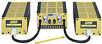
System Description: Each Modular Redundant DC Power System consists of three units: two identical power supplies connected to an Integration Module by 24” long cables. The Integration Module includes the diodes for isolating the power supply outputs, AC input switches, input fuses, LED ‘output present’ indicators, failure alarm circuits, and the umbilical cables which plug into the power supplies. Connections for the AC inputs, redundant DC output and failure alarm relays are on a screw terminal strip.
Operation: The diodes isolate a faulted supply output from the system output and pass only the output of the other power supply, without interruption of system output power during the transition.
The output voltage of the Primary supply is set approximately 0.2 volt higher than that of the Backup supply. Under this condition, the Backup supply’s series diode is not forward biased, and only the Primary supply delivers current to the load. However, if the Primary supply’s output decreases by more than 0.2 volt, the situation is reversed, and only the Backup supply delivers current. Each power supply includes an overvoltage protection circuit, to assure that neither power supply’s output will significantly exceed the nominal output voltage rating under any condition, including incorrect connection and adjustment.
Serviceability: Either power supply can be easily, safely and rapidly changed while the other supply continues to provide uninterrupted power to the load.
Alarm Circuits: The failure alarm circuits in the Integration Module operate relays, the contacts of which are available to control external failure alarms or other circuitry. The contact wiring of the two relays is connected in cascade, to simulate a single set of Form C contacts which switch if the output of either power supply decreases by more than 2.0 volts (3.0 volts for outputs over 48 volts) from the nominal rating.
Input Redundancy: Two isolated sets of AC input connections are provided, so that two independent sources of AC input power may be used, to obtain the additional benefit of input power redundancy. By feeding one input through a battery-backup power source (UPS), DC output power will be maintained even if both AC power sources should fail.
Overvoltage Protection: Automatic recovery. Each power supply contains an overvoltage protection circuit, to assure that neither power supply output will significantly exceed the nominal output voltage rating under any condition, including incorrect application and misadjustment.